
Parametric & Scripting Capabilities
TrueGrid® is both an interactive and batch mesh generator. The combination of the parametric features listed below transforms the mesh generation commands in TrueGrid® into a programming language for mesh generation. Commands are kept terse so that it is easy to navigate the session file that is automatically generated during an interactive session. A command input file is usually built from such a session file. This session file can then be rerun in batch mode to produce the same model or modified and run to produce a modified model. This is known as scripting. When arguments to some of the commands are substituted by algebraic expressions, the session file becomes parameteric and the file becomes a template to generate meshes for an entire class of problems. The more that arguements are replaced by parameters or algebraic expressions, the broader the class of problems that can be be solved with one session file.
A parameter can be used wherever a number is required. A parameter can be any alphanumeric symbol with the first 15 characters being unique among the set of all used parameters. A value is assigned to a parameter with the PARAMETER statement. A parameter value is referenced by preceeding the name of the parameter with the % character. You can use as many parameters as you want to control all aspects of the geometry and the mesh.
Change Mesh Density Locally
TrueGrid® is fundamentally parametric and this is evident in the multi-blocked structured parts. Compare the two meshes below. The mesh on the right has more elements in several regions. This is done by modifying the arguments to one command which initializes the part. By changing the number of elements in the cylinder command, the interpretation of all the commands that follow the cylinder command in the command input file are changed automatically.
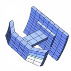 |
cylinder 1 2 6 7 8 ; 1 3 5 6 8 10 ; 1 3 4 6 7 9 ; |
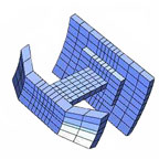 |
cylinder 1 6 10 11 12 ; 1 3 5 6 8 10 ; 1 3 4 10 11 13 ; |
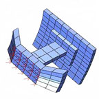 |
Even the boundary conditions automatically adjust to changes in mesh density and geometry. A force is applied to a face of the mesh. If the number of elements were changed, as in the above, then the force would be applied to the same region which would include the additional elements. |
Change Mesh Density Globally
The two meshes below are made from the same command input file. One parameter statement is changed to switch from one mesh density to another.
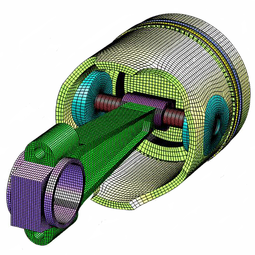
Rod & Piston Low Density parameter m 2 |
Rod & Piston High Densityparameter m 5 |
 |
 |
Expressions
More generally, any expression using numbers, parameters, mathematical operators, and functions can be used wherever a number is required.
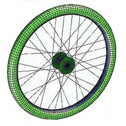
In this example a mesh of a wheel is constructed where the command input file has many expressions to parameterize the geometry. The radius of the tire is defined by the parameter rad2. The radius of the spokes, rad5, is defined by the expression [%rad1-%rad2]. So when the value for rad2 is changed the cross section of the tire, the rim, and the spokes automatically adjust.
 |
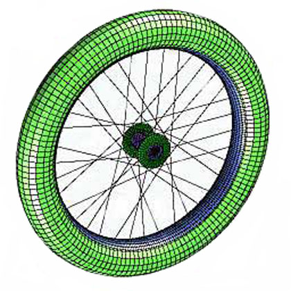 |
| rad2 is assigned the value of 25. | rad2 is assigned the value of 45. |
Parameterize Geometry
Geometry built with in TrueGrid® can be parameterized so that changes to the design of your mesh are as easy as changing a number in your scripting file.
In this example the TrueGrid® geometry library is used to create an ellipsoidal surface. The exponent is parameterized so that changes to the design are easy and changes to the mesh are automatic.
The following input was used to create the geometry:
para r .5
u0 0
u1 89.99997
;

sd 1 function  %u0 %u1 %u0 %u1 (2*cos(u)*cos(v))^%r;
			       (3*sin(u)*cos(v))^%r;
			       (5*sin(v))^%r;;;

sd 2 function %u0 %u1 %u0 %u1 (2*cos(u)*cos(v))^%r;
                               (3*sin(u)*cos(v))^%r;
                               (5*sin(v))^%r;rxy;;

sd 3 function %u0 %u1 %u0 %u1 (2*cos(u)*cos(v))^%r;
                               (3*sin(u)*cos(v))^%r;
                               (5*sin(v))^%r;ryz;;

sd 4 function %u0 %u1 %u0 %u1 (2*cos(u)*cos(v))^%r;
                               (3*sin(u)*cos(v))^%r;
                               (5*sin(v))^%r;rzx;;

sd 5 function %u0 %u1 %u0 %u1 (2*cos(u)*cos(v))^%r;
                               (3*sin(u)*cos(v))^%r;
                               (5*sin(v))^%r;ryz rxz;;

sd 6 function %u0 %u1 %u0 %u1 (2*cos(u)*cos(v))^%r;
                               (3*sin(u)*cos(v))^%r;
                               (5*sin(v))^%r;ryz rxy;;

sd 7 function %u0 %u1 %u0 %u1 (2*cos(u)*cos(v))^%r;
                               (3*sin(u)*cos(v))^%r;
                               (5*sin(v))^%r;rxz rxy;;

sd 8 function %u0 %u1 %u0 %u1 (2*cos(u)*cos(v))^%r;
                               (3*sin(u)*cos(v))^%r;
                               (5*sin(v))^%r;ryz rzx rxy;;
|
Parameter r set to 0.5  Parameter r set to 0.75  Parameter r set to 0.9 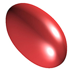 |
Update IGES Input
Changes to your IGES file can easily be reflected in your mesh. In order to build a new mesh with TrueGrid® so that it uses the new CAD geometry, simply change the session file using a text editor so that the IGES or IGESFILE command references the new IGES file. Then run TrueGrid®, using the session file as an input command file.
IGES GeometryA model is constructed in a CAD environment. The IGES file is written which contains the geometry for the mesh. |
Shoe MeshTrueGrid® is run to create the mesh by using the geometry found in the IGES file. |
 |
 |
Modified IGES GeometryIn the next step, the CAD operator makes a change to the shape of one of the surfaces in the model and writes a new IGES file for TrueGrid®. |
Modified Shoe MeshThe new IGES file is referenced in the TrueGrid® command input file. The model is ran again and the mesh is automatically updated to the new geometry. |
 |
 |
The Include Command
The include command will execute a list of commands found in a batch file. It is usefull when such a list of commands is set up parametrically so it can be reused for multiple situations. It is also a way to break a problem into components, build a model for each component, and sew them together with each include. It is a great way to organize your input to TrueGrid®. If you use parameters in an include file you must set values to those parameters before including the file. This is analagous to calling a subroutine or function in a programming language.
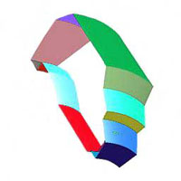
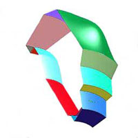
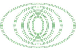
The following commands are the contents of an include file ring.inc. This small file creates a single part with the shape of an elliptic ring. The values of the parameters specify the form of the ring.
cylinder 1 3;1 91;-1;%r1 %r2;0 360;0;
lct 1 xsca %xs ysca %ys;lrep 1 ;
endpart
The input file below defines the parameters and calls the include file to form the set of rings shown to the right.
para r1 .7 r2 .9 xs .6 ys 1; include ring.inc para r1 1 r2 1.2 xs .8 ys 1; include ring.inc para r1 1.3 r2 1.5 xs 1 ys 1; include ring.inc para r1 2 r2 2.2 xs 1 ys .8; include ring.inc para r1 3.2 r2 3.4 xs 1 ys .6; include ring.inc merge |
 |
The If statement
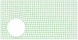
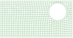
The if statement is used when the topology of the mesh needs to vary depending on parameters. For example, you may need a hole in the design of your mesh but it is unclear where the optimal position for that hole may be. You can use the if statement to change to tell tg what to do for different cases.
Here parameters are used to change the location of a hole in the mesh. An if statement is then used to determine where to place partitions in the mesh to delete the region for the hole. The parameter statements indicated the coordinates for the center of the hole are the only statements that need to be changed to run several variations of the mesh with the hole in different locations.
The following if statement was used in the input file to automatically change the location of a hole:
c Hole Beyond Top if ((%yc+%r+%del).gt.%y4)then para r [%y4-%yc-%del] x2 [%xc-%r*.707] x3 [%xc+%r*.707] y2 [%yc-%r*.707] y3 [%yc+%r*.707]; c Hole Beyond Bottom elseif ((%yc-%del-%r).lt.%y1)then para r [%yc-%y1-%del] x2 [%xc-%r*.707] x3 [%xc+%r*.707] y2 [%yc-%r*.707] y3 [%yc+%r*.707]; endif |
Parameter of x-coordinate set to 4 and
Parameter of x-coordinate set to 16 and |
Three Built in Macros
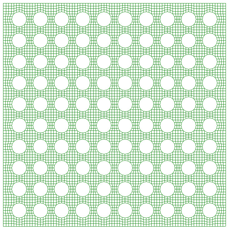
The FOR loop is used in a scripting file to repeat a process a prescribed number of times. Alternatively, the WHILE loop tests for completion each iteration. The WHEN macro, like the IF statement, is a conditional macro and is compatitble with the FOR and WHILE macros.
For example, if you had many holes in a pattern you could reduce the amount of effort with a loop. You can also create arrays in TrueGrid®. Arrays and loops work hand in hand, giving you the flexibility of any programming language.
Here, a simple example of a loop is used to illustrate this feature. A pattern of holes is needed as a feature in a mesh. The loop could be used to repeat the process of deleting regions of the mesh and projecting to a surface.
The input file with the loop in the block command is shown below:
para nindices 21; meshscal 2 block for i1 1 [1+2*%nindices] 2 %i1 endfor ; for i1 1 [1+2*%nindices] 2 %i1 endfor ; -1; for i1 1 [1+%nindices] 1 %i1 endfor ; for i1 1 [1+%nindices] 1 %i1 endfor ; 0; for i1 2 %nindices 2 for j1 2 %nindices 2 dei %i1 [%i1+1]; %j1 [%j1+1]; -1; sfi %i1 [%i1+1]; %j1 [%j1+1]; -1; cy [%i1+.5] [%j1+.5] 0 0 0 1 [cos(45)] endfor endfor |
Mesh with Pattern of Holes |
User Defined Functions
A function can be defined with any number of parameters. The function can then be used within an expression wherever an expression is evaluated to get a number.
In this example a function is used to change the z-coordinate.
|
|
A block command is used to form a simple 2D shell block 1 51;1 51;-1;0 50 0 50 0 |

|
A function statement is added to change the z-coordinate and achieve the resuling mesh def h(a,b) = min(50,max(10,a+b))
|
TrueGrid® Construction Functions
The following commands are built-in TrueGrid® functions that can be used to calculate coordinates. The results can be referenced using parameters. These are valuable tools that aid in finding exact coordinate when constructing a mesh.
- array - Define and load a multi-dimensional Array
- bulc - Butterfly Interior Vertex Loc|ation
- circent - finds the center of a circle
- crprod - finds the cross product of 2 vectors
- dc - Desktop Calculator
- distance - finds the distance between two points
- inprod - finds the inner product
- nodcor/snodcor - gets coordinates of a node
- pptcd - gets the coordinates from a projection to a curve
- ptcoor - gets the coordinates of a labeled point on a curve or surface
- jnp/sjnp - closest node to a point
- sp4pt - SPhere through |4| |P|oin|T|s
- subang - finds the subtented angle
- trapt - transforms a point
- tricent - finds the center of a triangle
- project - projects a point to a surface or the intersection of surfaces
- x(*,*,*) - first coordinate of a vertex in the mesh
- y(*,*,*) - second coordinate of a vertex in the mesh
- z(*,*,*) - third coordinate of a vertex in the mesh
TrueGrid® Automatic Parameters
The following parameters are automatically assign values and can be used in algebraic expressions like any other parameter.
- idxlist - List of full i-indices of the part
- jdxlist - List of full j-indices of the part
- kdxlist - List of full k-indices of the part
- nextmat - Next material number
- nextbb - Next Block Boundary ID number from BB command
- nextprt - Next part number
- node - Node number result from ajnp/sajnp and PICK>NODE functions
- element - Element number result from ajel/sagel functions
- xprj - X-component of projection
- yprj - Y-component of projection
- zprj - Z-component of projection
- xnrm - X-component of a normal
- ynrm - Y-component of a normal
- znrm - Z-component of a normal
- xcrprod - X-component from cross product crprod function
- ycrprod - Y-component from cross product crprod function
- zcrprod - Z-component from cross product crprod function
- inpro - Inner product from inprod function
- distance - Distance result from distance, circent, and sp4pt functions
- subang - Subtended angle result from subang function
- minmea - Minimum mesh quality measure
- maxmea - Maximum mesh quality measure
- mean - Mean of mesh quality measure
- standev - Standard deviation of mesh quality measure
- pi - Irrational constant circle circumference/diameter
- xboxmin - Minimum x-coordinate of the graphics containing box
- yboxmin - Minimum y-coordinate of the graphics containing box
- zboxmin - Minimum z-coordinate of the graphics containing box
- xboxmax - Maximum x-coordinate of the graphics containing box
- yboxmax - Maximum y-coordinate of the graphics containing box
- zboxmax - Maximum z-coordinate of the graphics containing box
- nextnode - Next node number (befor merging)
- nextlbrick - Next linear brick
- nextlshell - Next linear shell element
- nextlbeam - Next linear beam
- nextqbrick - Next quadratic brick element
- nextqshell - Next quadratic shell element
- nextqbeam - Next quadratic beam element
The functions lpil, trapt, tricent, bulc, circent, project, ptcor, pptcd, and nodcor/snodcor record their results in the following three parameters:
The functions circent, sp4pt, and project record their results in the following three parameters: