
TrueGrid® Projection Method
The projection method is a powerful tool designed to conform a mesh to any geometry. TrueGrid® meshes are shaped by projecting faces of the mesh onto surfaces. Surface imperfections are ignored and intersections of surfaces are automatically located. Coupled with the multi-block approach, this method allows TrueGrid® users to build quality meshes for even the most complex geometries and eliminates the need for the user to specify the bulk of the details when building their mesh.
The Projection Method is Easy
To use the projection method, specify the region of the mesh, select the surface to project to, then click on the Project button - and that's it. The projection method makes this Intersecting Pipes example easy. View TrueGrid® command file for Intersecting Pipes
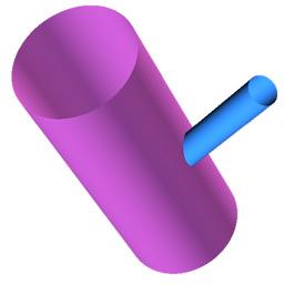 |
Create the GeometryThe first step is to define the geometry or import it from a CAD/CAM system. |
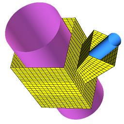 |
Build the TopologyNext, a crude approximation of the mesh is constructed using rectangular blocks. |
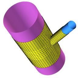 |
Project the MeshIn the final step, the rectangular faces of the mesh are projected to the appropriate surfaces. |
Achieve a Perfect Mesh With Imperfect Surfaces
Every CAD System and Solids Modeler has a tolerance when the surfaces are written to an IGES file. This can cause the surfaces to overlap or create a gap between the surfaces. TrueGrid® is able to conform to surface imperfections because the projection method ignores surface boundaries, gaps, and overlaps.
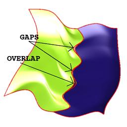 |
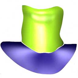
Imperfect Geometry With Gaps and OverlapsThis geometry is representative of a typical IGES file with geometry composed of several different surfaces that may have gaps and overlaps. |
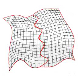 |
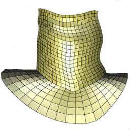
The Mesh Conforms to the GeometryThe surfaces are combined into one surface within TrueGrid®. The projection method is used and the result is a smooth mesh across the geometry. Mesh lines are not constrained by surface boundaries, and gaps and overlaps are ignored. |
TrueGrid® Automatically Finds the Intersection of Surfaces
In contrast to the previous example, where we did not want a mesh line to follow surface boundaries, this example requires that a mesh line does follow the surface boundaries. TrueGrid® handles this case just as elegantly by ignoring the gaps and automatically intersecting the surfaces.
 |
Surface Intersection with GapsThis geometry is composed of two different surfaces that do not meet. |
 |
Mesh Line Placed at IntersectionThe curve that is formed from the intersection of the two surfaces is an important feature that requires a mesh precisely at that intersection. The projection method automatically finds the intersection of these two surfaces and places boundary nodes along that intersection. |