
AUTOMATIC RIVET HOLES: XYZ Scientific Applications, Inc. has a multi-year effort in automatic multi-block structured quad shell and hex solid mesh generation. New features in TrueGrid® Version 3 integrate seamlessly with all the previously existing features that has made TrueGrid® the best in quality quad shell and hex solid mesh generation. For example, the new hole command inserts a hole in a block structured mesh by simply defining a cylinder.
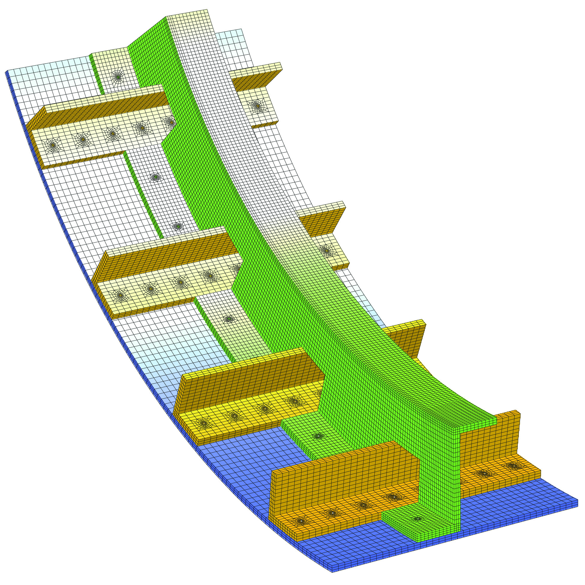 Multiple Block Structured Mesh Parts With Many Rivet Holes Inserted Automatically
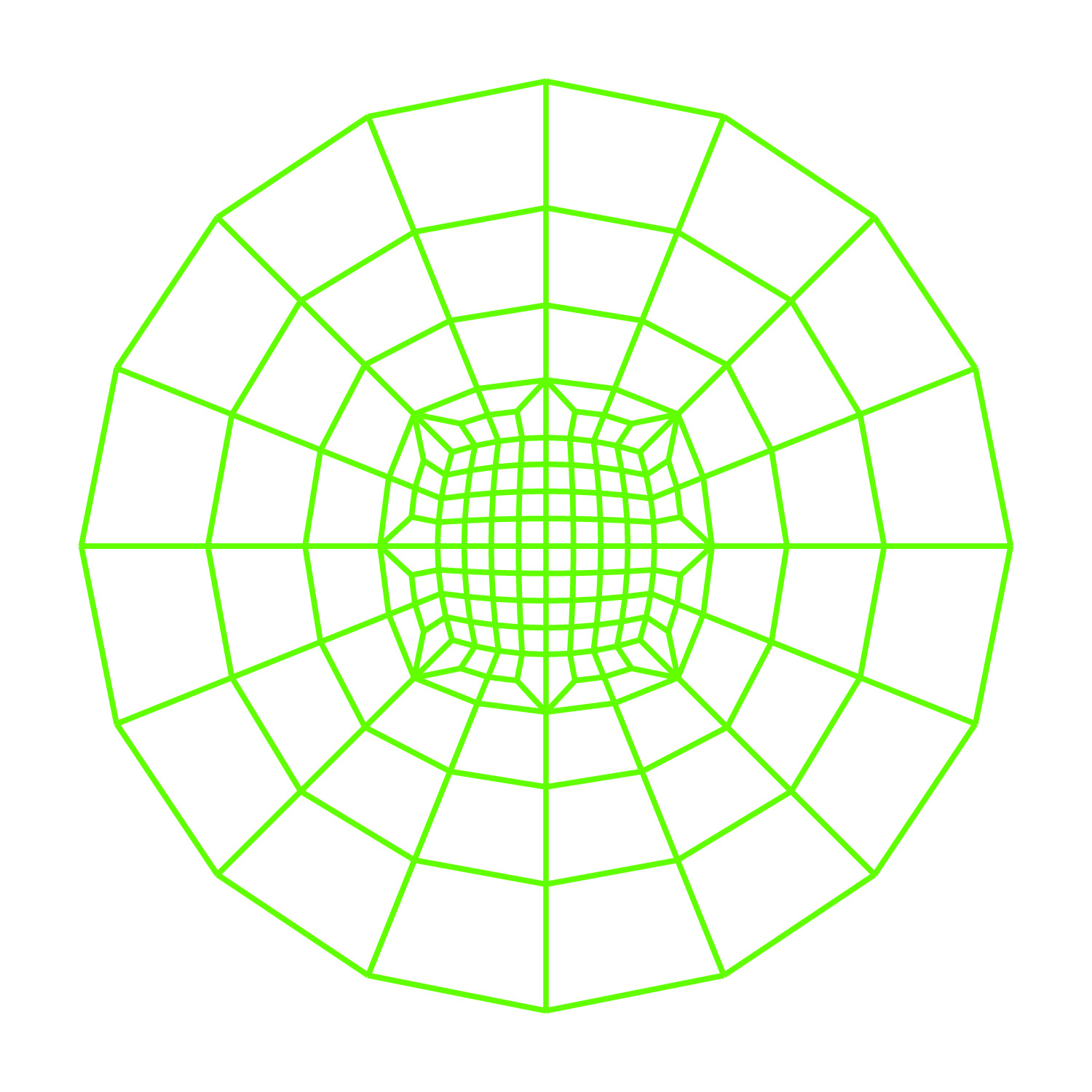
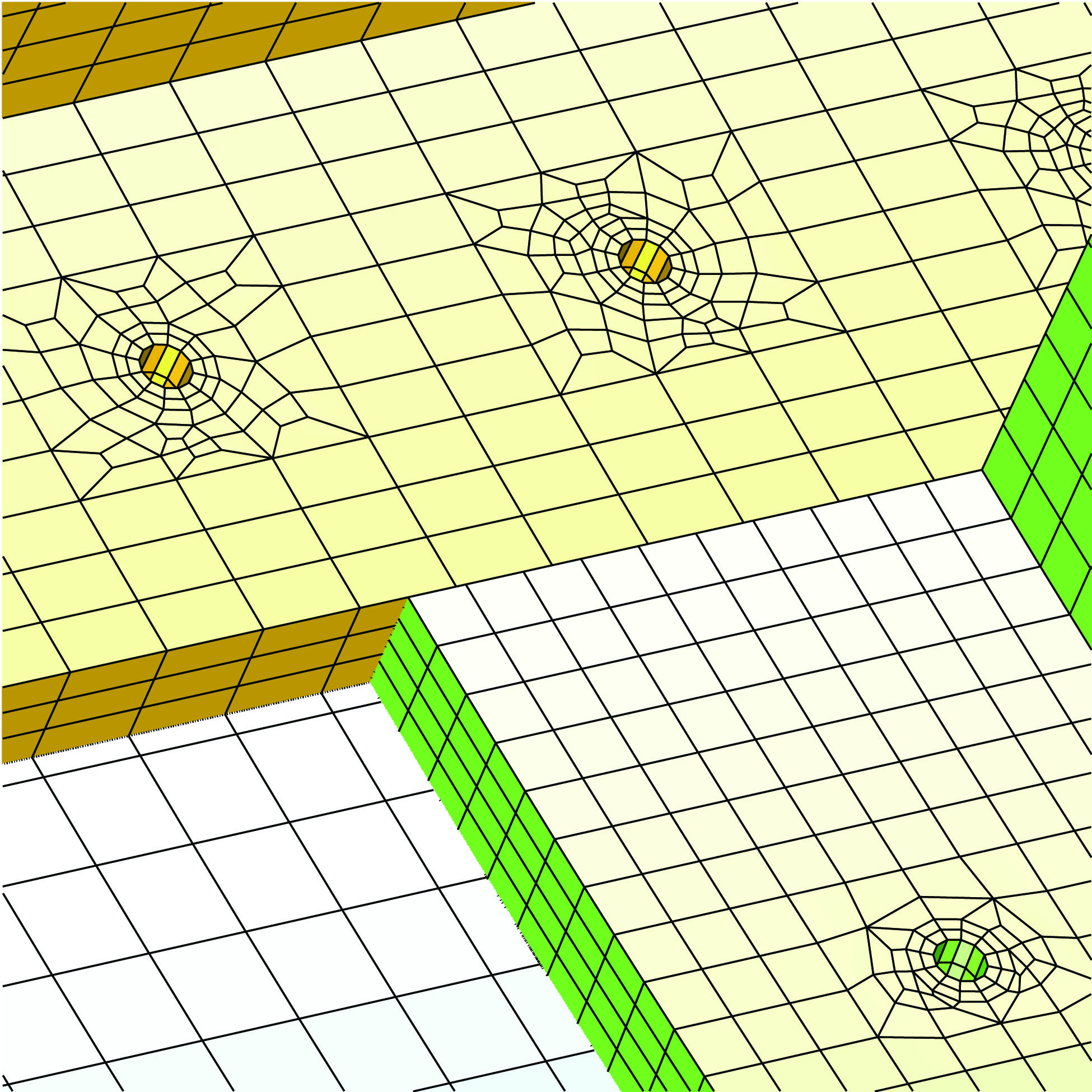 Closeup of Several Rivet Holes Showing a High Quality Annulus Mesh Around The Holes
AUTOMATIC QUAD SHELLS: XYZ Scientific Applications, Inc. Is committed to providing the best quality automatic quad shell and hex solid mesh generation tools in TrueGrid®. A new feature is under development to automatically mesh a composite surface with all quad shell elements. The boundary can be formed using a curve or by selecting the exterior boundary curve of the composite surface. Perhaps the most significant aspect of this new feature will be that the quality of the all quad mesh will not be affected by the quality of the boundary edges of each component surface. In particular, the surfaces do not have to meet perfectly and the shape of the boundary edges will have no affect on the shape of the interior elements. This new feature will soon be out of the development phase and will enter the testing phase. Look for a new release of TrueGrid® in the near future with this feature.
PROGRAMMING AUTOMATIC MESH GENERATION: Control statements can be used to automate the generation of the geometry and the mesh. For example, if many holes are needed, the (iterative loop) FOR statement can be used to automate the process of inserting the holes. The mesh shown in the previous pages has 4 rows of holes with 8 holes in each row which can be automated using 2 embedded loops:
FOR rownumber 1 4 1
FOR colmnumber 1 8 1
Hole command
endfor
endfor
The WHILE statement is also an iterative loop, but with a more general criteria for stopping.
The (conditional) WHEN statement is useful when developing a parametric mesh. The WHEN statement makes it possible to choose various topologies, depending on parameter values.
The BREAK command changes the flow of commands by jumping out of the scope of a FOR, WHILE, or WHEN statement.
The ARRAY command defines an array of floating point values that can be used just like any parameter in TrueGrid®. For example, a multi-dimensional data array might be needed within the FOR or WHILE loop .
These commands are executed in TrueGrid® first so that they can be embedded within other commands. In other words, they can be used to generate data as arguments for other commands. The FOR, WHILE, WHEN, ARRAY, and BREAK commands in TrueGrid® provide the control needed to transform a single instance session file into an automatic mesh generation tool for a broad class of problems. New functions and automatic parameters have also been added to this version to aid in parameterizing the mesh.
 Automatic Intra-Part Transitions
INTRA-PART TRANSITION BLOCK BOUNDARY: In previous versions of TrueGrid®an automatic transition between two dissimilar regions required that each region be in a different part. It also required that the master side be in the part that preceded the part with the transition elements. In the new version of TrueGrid® the master and transition sides of the interface can be in the same part. The simple example here shows automatic transitions within one part.
HISTORY TABLE FILE: This new feature will be very useful to experienced TrueGrid® users. The typical approach to building a parametric model is to maintain a session file of commands, originally introduced interactively. However, the session file written by TrueGrid® , called tsave, has not only all of the important commands preserved in the order that they were issued, but also all of the mistakes and complications that occur during an interactive session. TrueGrid® takes numerous steps to clean up this stream of commands before writing it into a file called tghist. One can take advantage of both files to produce, via a text editor, a complete and understandable session file.
LONG FILE NAMES INCLUDING SPACES IN THE NAME: The length of file and path names have been extended to 256 characters. In addition, spaces can be included in both the file and path names. In particular, it is now possible to install TrueGrid® into the WINDOWS “Program Files” directory which was not possible in the past because of the space in this directories name.
QUADRATIC BEAMS: Quadratic beams (i.e. beam elements with 3 nodes) can now be generated in the same way that linear beam elements (i.e. beam elements with 2 nodes) are generated. There are two ways to generate beams in TrueGrid®. In the first method, a shell or solid part is formed and then beam elements can be formed along the mesh edges of the part. In the second method, beam elements are formed along a 3D curve. In both cases, precede the beam generation using the quadratic command to generate quadratic beans instead of linear beams.
GRAPHICS ACCELERATORS AND OPENGL: The interface to graphics accelerators through OpenGL has been completed. At this point we know of no problems with any graphic accelerators. In particular, TrueGrid® works well with the Nvidia Quadro Pro line of graphics accelerators. It has been our practice to supply two executables of TrueGrid®, one with an interface to the graphics accelerator and one that does not rely on a graphics accelerator. On a WINDOWS system, the executable called tg.exe takes advantage of the graphics accelerator with OpenGL. The executable called tgw.exe (w for WINDOWS API) does not. On a MAC/LINUX system, the OpenGL version is called tg and the non-OpenGL version is called tgx (x for X-Windows). If a 64 bit version is desired, add the letter “d” to the name (d for double precision). On WINDOWS, the double precision versions are called tgd.exe and tgdw.exe, respectively. On a MAX/LINUX system the double precision versions are called tgd and tgdx, respectively
MORE EFFICIENT USE OF MEMORY: A problem in the use of memory, especially for a double precision version of TrueGrid® with large memory requirements, has been resolved. A rule of thumb is approximately 120 bytes per node in single precision. Double that for a double precision version of TrueGrid®. TrueGrid® is capable of generating large meshes. On a 32 bit system one might be able to generate a 15,000,000 node mesh. On a 64 bit version, there is virtually no limit. However, there is a great expense in writing the the mesh into a specific format. Until there is a need for much larger meshes, there will always be a bottleneck in writing the output file.
OUTPUT FORMATS: There are some new formats supported by TrueGrid® such as KIVA3v, CFX5, SAP2000, and MPACT. Improvements and updates have been made for the following output options: LSDYNA, EXODUSII, SAMI, ABAQUS, STARCD, KIVA 4, CFX 4, LLNL DYNA3D, TOPAZ3D.
NEW USER’S MANUAL: All of these new features and more are described in detail in the new TrueGrid® Version 3 User’s Manual.