
Automatic Rivet Hole generation
Rivet holes can be inserted automatically. The cylinder that forms the hole must be (nearly) orthogonal to the face of the block mesh. The block mesh must be (nearly) orthogonal. This command works for both bricks and shells, linear and quadratic.
This command is not needed if the ideal topology for the hole has been built into the design of the block part. But when the mesh density of the block part does not match the mesh density of the desired hole, if you want an easy way to form a symmetric plug around the hole, if you have many holes to add, or if you need to add holes after the model has been completed, then the hole command will be ideal. This is an automatic hole capability in that a region around the plug is re-meshed to form a transitional region between the plug and the original block mesh. If there are several holes in proximity, then the region around the plugs will form a single transitional region between the plugs and the surrounding hex mesh.
hole insert a cylindrical hole
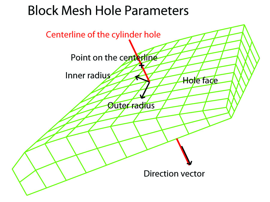
hole region x0 y0 z0 xn yn zn radius options ;
where the region must be a face of the part.
where (x0,y0,z0) is a point on the centerline or axis of the cylindrical hole
where (xn,yn,zn) is the axis direction vector
where radius is the (outer) radius of the cylindrical hole
where option can be any or all of the following:
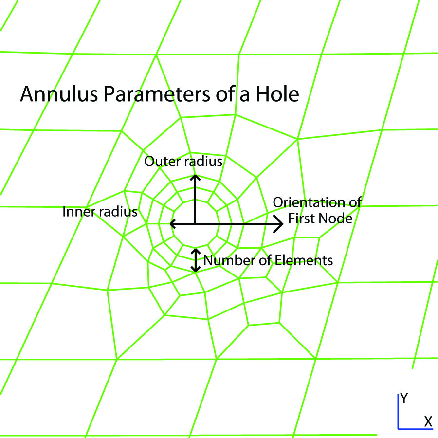
inr radius for the inner radius of an annulus
fn xd yd zd for the orientation of the first node in the outer cylinder
net n for the number of elements in the thickness of the annulus
ang theta for the angle of the conic countersink
 Block before hole inserted |
|
 Block after hole inserted |
|
|
||
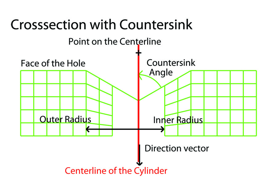 Countersink Diagram |
|
 Hole with countersink |
Remarks
The hole command creates a cylindrical hole in a block part. A ring of 12 hex elements are formed around the hole to produce a symmetric mesh around the hole. The two faces of the block part, that which is identified by the region and the opposing face of the block must intersect with the cylinders identified in the hole command. Both faces must be projected to a surface. The mesh around the hole and the hole are not visible until after entering the merge phase. This is because the mesh around the hole is not formed until the part is ended, since many commands can effect the shape of the block part before the mesh around the hole is formed.
The process used to form the transition between the block mesh and the hole annulus starts with an automatically formed all quad mesh on the hole face. These quad faces are then extruded in the direction of the cylinder axis to form hex elements filling the gap. Because this is an extrusion process, there are some obvious rules to follow. Two holes must be far enough apart so that a reasonable mesh can be formed between them. Holes can only be applied in one direction. In other words the holes cannot cross. One hole cannot be inside another. The hole must be contained within the boundaries of the part.
The quality of the mesh that transitions from the block mesh to the hole can be low. This is unavoidable when the mesh density between the existing block mesh and the boundary of the hole are very different. To improve the quality, try changing the mesh density of the block mesh. Also, try changing the orientation of the first node. It is also possible to convert some of the hex elements to prism (wedge) elements. Two parameters control the substitution of wedge solids for hex solids in the region between the cylinder hole and the original block structured mesh.:
arquah - ratio for the largest aspect ratio for a quad face in the region between the outer cylinder and the block mesh. If this parameter is set to a number less than 1, then this parameter will not be used to determine the conversion to wedge (prism) elements.
esquah - length for the smallest edge length for a quad face in the region between the outer cylinder and the block mesh. If this parameter is set to zero, then this parameter will not be used to determine the conversion to wedge (prism) elements.
When arquah is greater than 1 and when esquah is positive, than any quad that has an aspect ratio greater than arquah and an edge length less than equal to esquah will be converted to a triangle face and the resulting extruded solid elements will become prism (wedge) elements.
The rfholes command can be used to to enlarge the region that transitions between the block mesh and the hole annulus.
There are some limitations on the shape of the hex mesh in the area of the hole. In particular, the mesh lines of the block part must run nearly parallel to the axis of the cylindrical hole. This requirement will be relaxed in future versions.
There are some limitations on the surfaces being used for projection of the face identified in the hole command. The surfaces that can be used here are:
1. all IGES surfaces
2. parameterized surface (function)
3. sphere (sp)
4. ellipsoid (er)
5. tabular (mesh)
6. ruled2d (rule2d) and ruled3d (rule3d)
7. torus (ts, toru)
8. swept (swept)
9. polygon (faceset)
10. pipe (pipe)
11. blended (blend3, blend4)
12. splines (csps, bsps, nrbs, hermite)
13. interpolated (intp)
14. rotated 2D (cr,crx,cry,crz) and 3D (r3dc) curves
15. composites (sds) from any of the above
Basically, unbounded surfaces cannot be used. Also, any surfaces that have edges that are degenerate or that meet with another edge of the same surface cannot have a hole that crosses or contains one or more of these edges. For example, a sphere, cylinder or torus has edges that meet (i.e. they are periodic). Do not confuse this with a composite surface where two or more surfaces have common edges. This hole feature works well where edges from different surfaces meet.
Examples
The following is an example when many close holes are formed in a block with a coarse mesh.
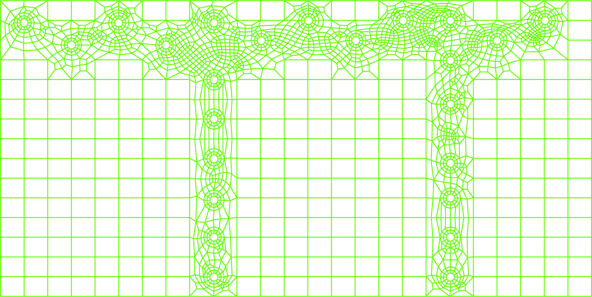
Space between multiple holes and block mesh sewn together
In this next example, 39 surfaces from an IGES file are composed. Then a shell mesh is projected to this composite surface an a hole is automatically inserted, using the hole command.
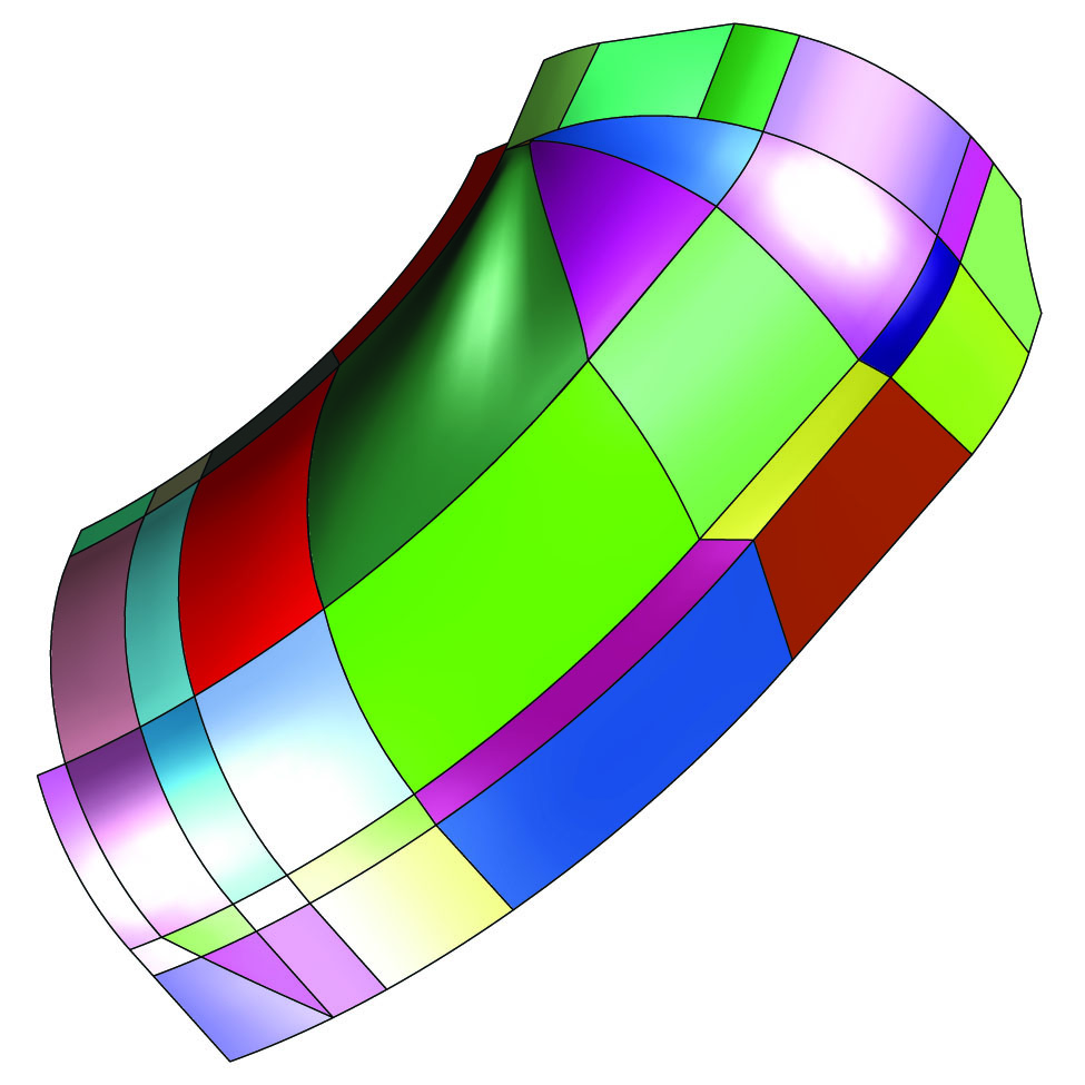 Composite surface from 39 surfaces |
|
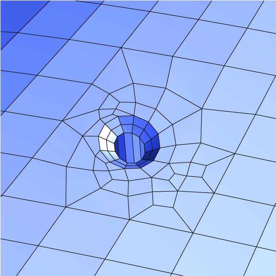
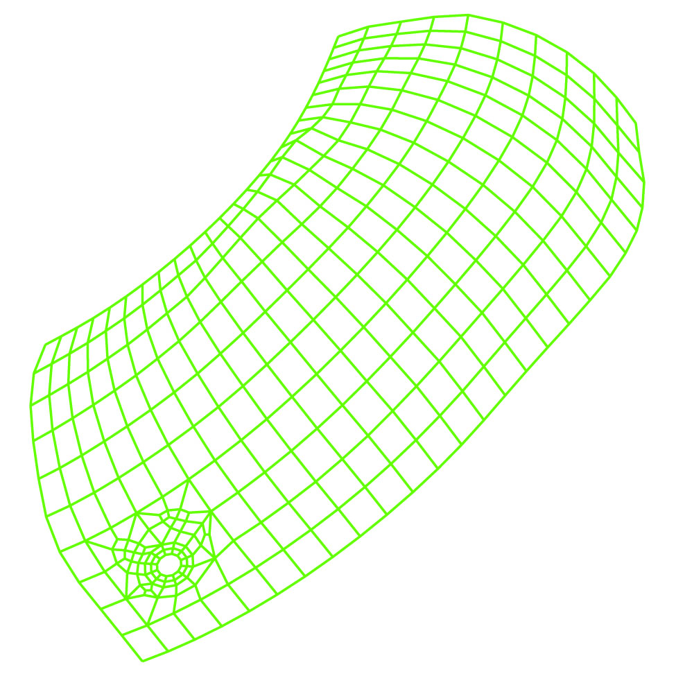 A single hole inserted into a shell mesh
|
rfholes relative factor for holes
rfholes factor
where factor is a number greater than 1
Remarks
The default is 1.95. This factor determines the size of the region in the block mesh that is carved out for the opening to be filled by the hole command. This factor is multiplied by the outer radius of the hole and the region carved out of the block mesh must accommodate the cylinder with this radius. By changing this number, the resulting automatic mesh that fills in the region between the annulus of the hole and the boundary formed by the carved out region in the block mesh will change. In most cases, if there is more room in the transition (larger factor) region (the automatic mesh), the higher the quality of the mesh. This is not an absolute and if the quality is not acceptable, then run some experiments with various factors. For higher quality, it may be necessary to increase (or decrease) the mesh density of the block mesh.
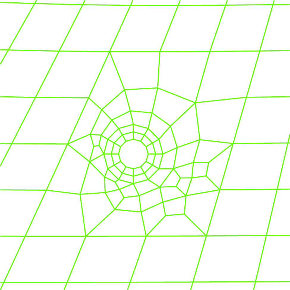
Example
In this example on the right, the relative factor is set to 3. This means that a cylinder with a radius 3 times the outer radius of the hole was used to determine the block carved out of the block mesh before it was filled with a transition mesh between the block mesh and the annulus of the hole.
 rfholes set to 1.95 (default) |
|
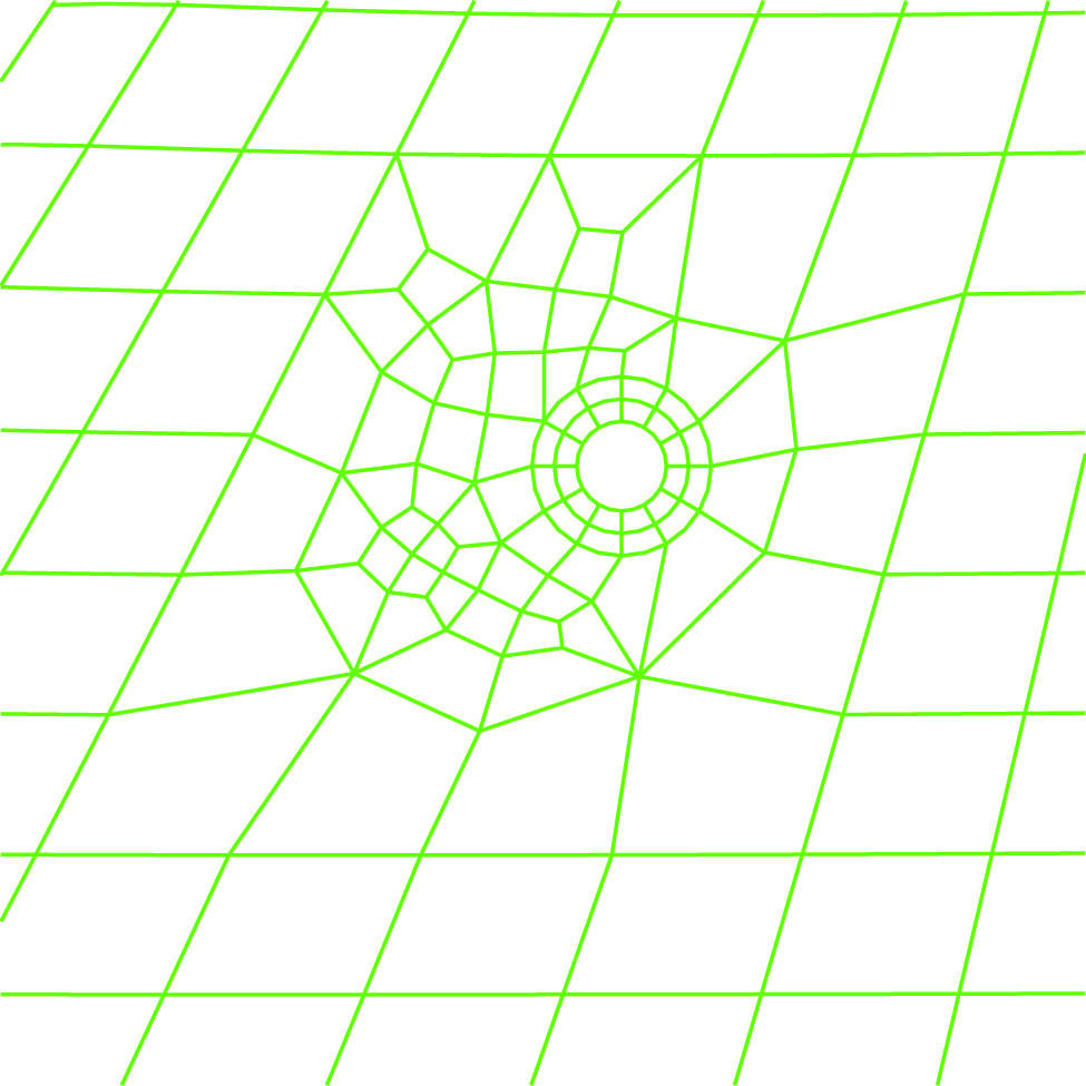 rfholes set to 3 |
arquah aspect ration that triggers triangles around holes
arquah aspect_ratio
where aspect_ratio is the maximum aspect ration for a quad face
Remarks
The default is infinite. Set arquah to zero to return it to the default.
This parameter controls the generation of triangles on the hole face. Triangles are inserted in the transition between the block mesh and the hole annulus after it has been filled with quads. Any quads with and aspect ration greater that arquah will be replaced by triangles.
A quad is converted to a triangle by collapsing the smallest edge of the quad. If this edge is along the boundary (i.e. the interface with the block mesh or the interface with the hole annulus), then the quad will not be converted to a triangle.
Example
Compare the left (no triangles) and the right (4 triangles) with reduced aspect ratio.
|
arquah set to infinity (default) |
|
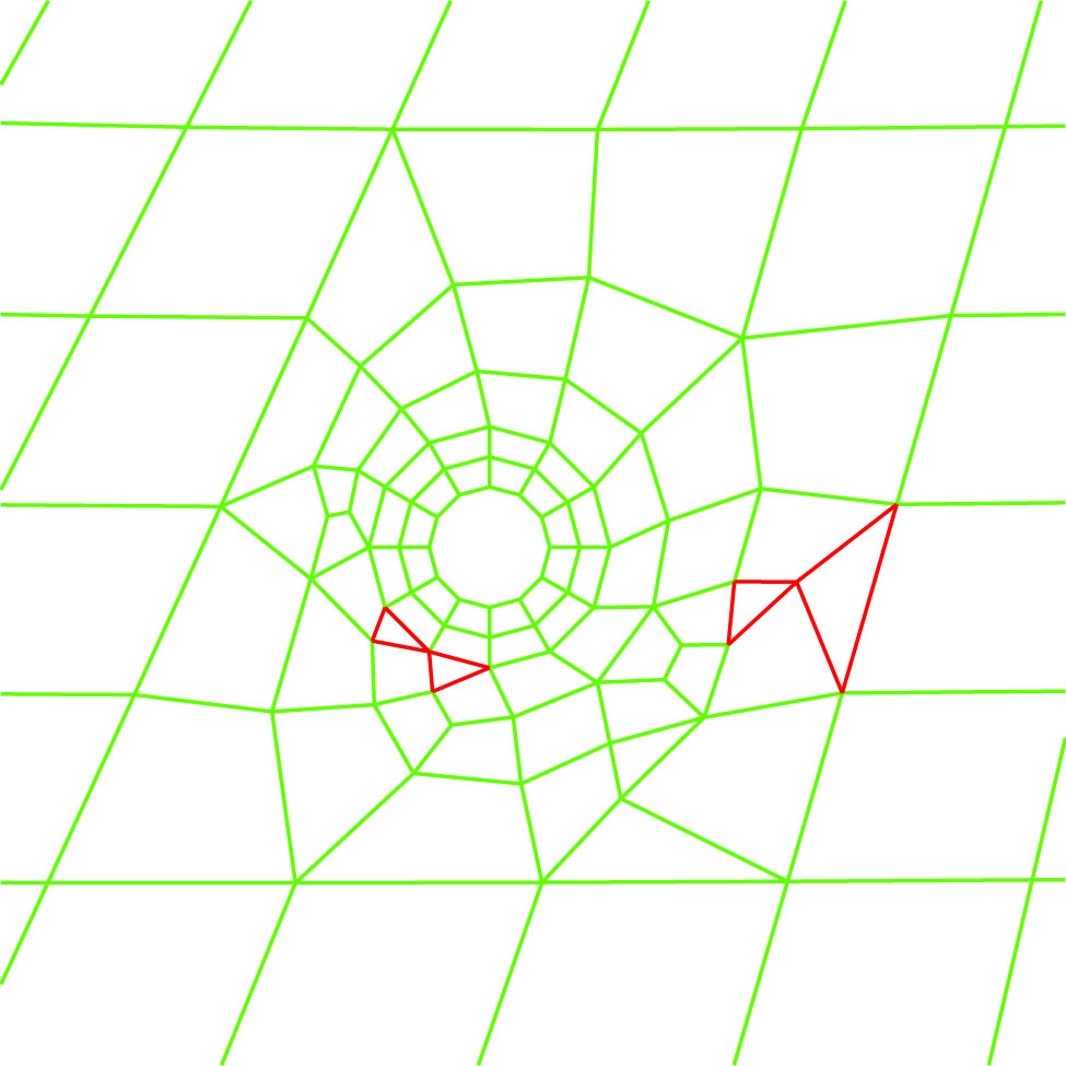 arquah set to 3 |
esquah edge size that triggers triangles around holes
esquah size
where size is the minimum edge size allowed for a quad.
Remarks
The default is zero.
When the hole command is used, after the quads are formed to fill the region between the block mesh and the hole annulus, the quads are inspected. If any quad has an edge less than or equal to the specified minimum, it is marked to be replaced by triangles.
A quad is converted to a triangle by collapsing the smallest edge of the quad. If this edge is along the boundary (i.e. the interface with the block mesh or the interface with the hole annulus), then the quad will not be converted to a triangle.
Example
The only difference between the two meshes below is the use of the esquah command.
|
esquah set to zero (default) |
|
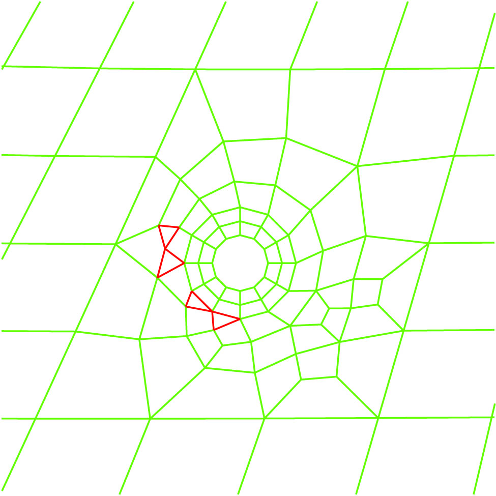 esquah set to 5 |
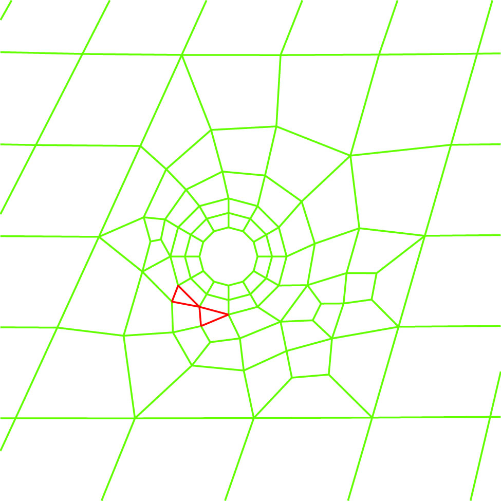
arquah and esquah set
In this last example, both arquah (set to 2) and esquah (set to 4) work together to produce this mesh.