TrueGrid® Is Ideal For Parametric Studies
A parameter can be used wherever a number is required. A parameter can be any alphanumeric symbol with the first seven characters being unique among the set of all used parameters. A value is assigned to a parameter with the PARAMETER statement. A parameter value is referenced by preceding the name of the parameter with the % character.
The two meshes below are made from the same command input file. One parameter statement is changed to switch from one mesh density to another.
|
ROD & PISTON - LOW DENSITY
parameter m 2
          n 1
          t 1
          u 1;
(71K) |
|
ROD & PISTON - HIGH DENSITY
parameter m 5
          n 4
          t 3
          u 2;
(82K) |
More generally, any expression using numbers, parameters, mathematical operators, and functions can be used where ever a number is required.
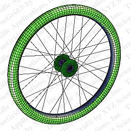
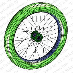
In the wheel example, the command input file has many expressions to parameterize the geometry. For example, the parameter rad2, the radius of the cross section of the tire, is assigned the vale of 25. When TrueGrid® is run using this command input file, it generates the first mesh. When the rad2 parameter is assigned the value of 45, then TrueGrid® generates the second mesh.
The projection method of mesh generation represents a form of parametrics. The following steps are taken.
| Suppose a model is constructed in a CAD environment. The IGES file is written which contains the geometry for the mesh. |
|
|
TrueGrid® is run to create the mesh by using the geometry found in the IGES file. |
| In the next step, the CAD operator makes a change to the shape of one of the surfaces in the model and writes a new IGES file for TrueGrid®. |
|
|
In order to build a new mesh with TrueGrid® so that it uses the new CAD geometry, simply change the session file using a text editor so that the IGES or IGESFILE command references the new IGES file. Then run TrueGrid®, using the session file as an input command file. |
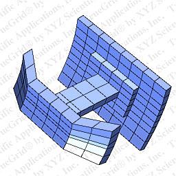
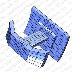
TrueGrid® is fundamentally parametric and this is evident in the multi-blocked structured parts. Compare the two meshes below. The second mesh has more elements in several regions. This is done by modifying the arguments to one command which initializes the part. By changing the number of elements in the CYLINDER command, the interpretation of all the commands that follow the CYLINDER command in the command input file are changed automatically.
|
|
  CYLINDER
    1 2 6 7 8 ;
    1 3 5 6 8 10 ;
    1 3 4 6 7 9 ;
|
  CYLINDER
    1 6 10 11 12 ;
    1 3 5 6 8 10 ;
    1 3 4 10 11 13 ;
|
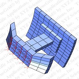
Even the boundary conditions automatically adjust to changes in mesh density and geometry.
A force is applied to a face of the mesh. If the number of elements were changed, as in the above, then the force would be applied to the same region which would include the additional elements. |
|
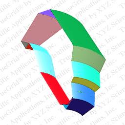
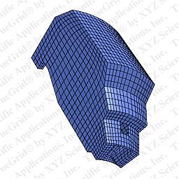
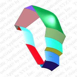
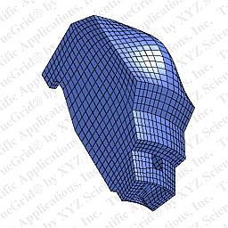
In this last example, all of the features discussed in this page are used to build a template command input file for TrueGrid®. This makes building a mesh of the air about a jet engine nacelle virtually automatic. A model of the nacelle is constructed using a CAD/CAM system or a solids modeler. An IGES file is written. Then six (6) parameters must be assigned appropriate values in the command input file. TrueGrid® is then run to create a mesh like the one below.
|
AIR ABOUT JET ENGINE NACELLE
(90K) |
Questions, comments, suggestions
Copyright © 1996-2013 XYZ Scientific Applications, Inc. All rights reserved.